Help for SwayStar™ (4.7.3.265)
Test subjects may have varying degrees of stability when standing. It is advisable to have an assistant or two, if necessary, on hand to help during the test procedures. The belt is put on first, with the sensor cable hanging down, and then the flaps are tightened. With the test subject standing and with arms slightly extended away from the sides of the body, wrap the belt around the torso of the test subject with the flap closures at, or near, the diaphragm. Do not secure the belt too tightly but insure that it is firmly held in place, then tighten the belt using the flaps. Allow the test subject to take a couple of steps so that he/she feels comfortable with the equipment.
Note: tasks are performed without shoes, preferably barefooted.
· Turn on SwayStar™. The switch is located on the sensor box of Model 2 or at the back of the power supply box for Model 1.
· The two icons on the upper left-hand edge of the screen will initially show grey. Once the communication handshake has occurred between the hardware and software, one of the icons will appear in colour (magenta). This usually takes between 5-10 seconds. If this does not happen it is important to check the sensor function in Options (see 3.2.3, below).
Model 2B users MUST establish the Bluetooth connection for the first time before the sensors can be tested via the wireless communication. The connection with cable (no CE Mark) is tested as described below – 3.2.4 Checking Sensor Function . Before establishing the Bluetooth the software driver for the dongle must be installed and the SwayStar™ software undated ( see 3.1.5 Software Installation).
To establish the Bluetooth connection.
Note: The Bluetooth™ standard contains several search and authorisation procedures which are recognizable in form of process delays (some 10 seconds). So if your PC seems not to react just wait!
Don’t click on the close cross
of the bubble. Click inside the
bubble. The authorisation dialog appears.
The Bluetooth™ application wants to know the PIN[1] of the detected
Bluetooth™ device. The PIN is
identical to the serial number of your sensor box, e.g. “SwayStar-Box SN1004”
has the PIN “1004”.
Once you have established the Bluetooth connection, the sensors can be checked.
The procedure above has to be executed only once at first installation. Even if you unplug the Bluetooth Dongle the next time you plug in the dongle again (at the same USB connector) to your PC it will remember the port number.
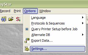
From the Main Menu, select Options and left click on Settings. The Settings window displays the option to choose the Model Type of Sensors and test the communication.
Model 0 uses the computer mouse movements plus the output of a pseudo-random generator for demonstrating recordings without sensors. It is the default sensor type if no sensors are connected.
Model 1 is a BII prototype system using 2 COM ports with a NI 485 interface.
Model 2 uses 1 COM port with a custom-built interface.
Model 2B is a standard production unit which uses a virtual Bluetooth COM port and 1 COM port when the communication cable is employed. The cable cannot be used for communication when the unit has a CE mark.
Model 3 is another BII prototype system.
It is possible to reverse the polarity of the recording by ticking in the reverse polarity box. Generally this is not done. The standard polarity is backward pitch and left roll set negative.
Select the model type for which you want to test the sensor function.
If the user has acquired rights to use the BalanceFreedom™ feature of the software, the box under the sensor options should be checked.
·
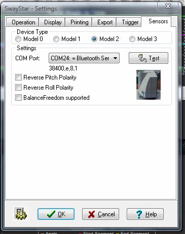 Make sure a COM port is
selected from the available list. It may be necessary to choose another port in
the list if one COM port indicates a sensor communication failure. An alternative
is to click on the animated SwayStar image to discover the available channels.
This discovery function looks first for Bluetooth devices available and allows
the user to select one in list.
Make sure a COM port is
selected from the available list. It may be necessary to choose another port in
the list if one COM port indicates a sensor communication failure. An alternative
is to click on the animated SwayStar image to discover the available channels.
This discovery function looks first for Bluetooth devices available and allows
the user to select one in list.
· For Model 2B users the COM port to use will have been displayed when setting up the Bluetooth communication for the first time. (see section 3.1.5)
· For Model 1 systems the COM ports to use were displayed when testing the NI 485 card.
· Left click on the Test button (for Model 1 systems separate Pitch and Roll test buttons are used).
· If the sensors are functioning, a message will appear:
· “Communication interface and sensors are working properly!” With Bluetooth systems this test includes a search for the Bluetooth device and may take several seconds.
· If the sensors are not functioning, a message will appear: “The sensor test failed! Check the cables, and power off and on the device!” (You may also wish to review the log report that appears in red under the message.)
Note: If sensor test fails, either no power is available or the correct COM ports from those available in the list have not been selected. If only one sensor works for Model 1 systems either the cables to the failed sensor are not connected properly, the COM port has not been selected correctly or the sensor itself has failed.
Note: SENSORS RARELY FAIL!
Every time the SwayStar™ Model 2 with Bluetooth is started the sensor box should be switched on first and then the SwayStar™ software started. The Bluetooth authorization bubble will appear and the authorization pin must be entered.
It is usually not necessary to test sensor function each time the program is started. The icons that appear on the upper left-hand side of the Main Screen indicate that the sensors are connected, powered and functioning.
If sensor communication fails during a recording then you will be asked to accept, retry or abort the recording unless the battery sensor was too low for the Model 2B system to operate.
All relevant fields should be completed when entering a subject for the first time.
· If you have entered Manage and a subject’s (patient) name appears in the field, you may sort by ID or by last name (Name).
· Alternatively, you may look up previous subjects, select edit, see next in list or add a new patient.
· To add a new subject, select New then enter the relevant patient details in the Patient window and select OK. This will close the window but maintain the patient record in memory. The minimum data that needs to be defined is Last and First name and Date of Birth.
· When proceeding to record data, the most recently selected subject in the Patient Data window will be the current test subject.
·
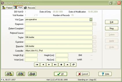 To complete the entry,
select the Visit tab and supply the relevant information. Add the subject’s
weight, height and waist and hip measurements if you wish to have these stored.
First-time subjects will have no records to review.
To complete the entry,
select the Visit tab and supply the relevant information. Add the subject’s
weight, height and waist and hip measurements if you wish to have these stored.
First-time subjects will have no records to review.
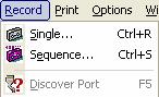
From the Main Menu, select Record and left click on Single.
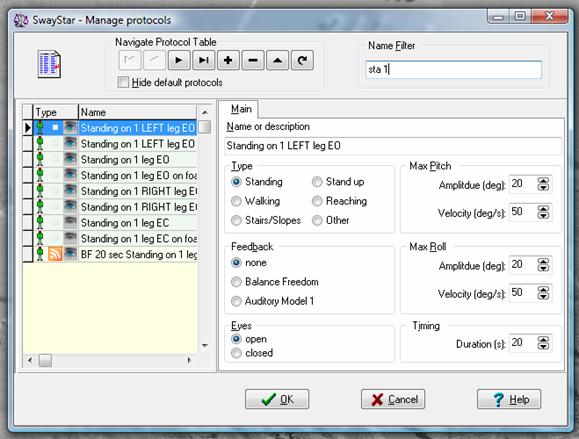
· The Select protocol window displays the available test protocols and shows the various parameters that have been set. The settings for amplitude, velocity and duration have been chosen to cover most cases of individual variations. It is not necessary to alter these settings as the off-line analysis provides auto-scaling. The pre-defined factory protocols (highlighted in green) do not allow settings to be altered.
· Use the Name Filter field, to enter part of the protocol name in order to search for the desired protocol, and then double left click on the desired test protocol.
· The Record window will open showing the protocol that was selected
Note: The subject is listed in red in the recording window if the visit of the last selected subject is more than 24 hours old.
Note: The word “faked” is automatically added to the record name if the Model 0 sensor type (random generator is used).
Note: Trying to record with an auditory Model 1 feedback or BalanceFreedom™ protocol if either of these feedback controllers are not connected and switched on will cause an error message to appear when the recording is started unless the feedback settings have been suppressed in the protocol.
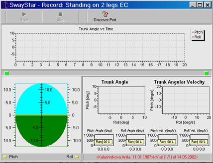
To begin recording, click Start (top left) or press [ALT] + [S] and the recording will be started after a short delay. Triggered starts (see section 5.4.6 Trigger) start with no delay.
A number of indicators inform the user that the hardware is functioning correctly.
An indicator left and below the time plot indicates system power is sufficient if green. If it is not, a recording can not be started.
Another indicator below the time plot and to the right indicates the rechargeable battery status for Bluetooth function (if it is in use). Green is sufficient power, a flashing yellow critical and when red no recording is possible.
Two further indicators show the sensor status. These are marked Pitch and Roll and are green when the sensors have sufficient power, yellow when power is insufficient, and red when the sensors are not functioning, that is not switched on.
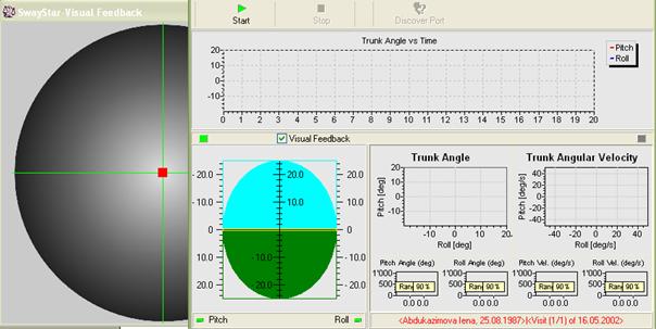
If the user has the Balance View Option, they can click on the “Visual Feedback” box and enable the visual feedback display. This display will fill the whole screen (or the screen of an auxiliary monitor) where the recording starts. It is downsized before recording starts.
· You may stop the recording at any time by clicking the Stop button or pressing ALT and t on the keyboard. If you stop before 1.26 sec, insufficient data will be available for analysis. An error message informs the user that such a recording will not be stored and it must be redone.
· As the recording progresses, a real-time display appears and on-line analysis.
· You may check the correct orientation and recording polarity of the sensors in real time. Pitching backwards (or simply tilting the sensors) should cause the pitch traces to move down, as well as the display of the artificial horizon. Rolling left should cause traces in the x-y plots to move left, the horizon right, and the roll trace in the time plot to move down. If this is not the case, contact the manufacturer before checking the reverse polarity box under Sensor settings.
Note: In order to view the on-line display in real time, the recording window should not be maximized or resized before or during recordings. Also for some Laptop computers recordings should not be run on battery power.
Triggering an external device
Model 2 SwayStar™ users can use the Start and Stop command signal to synchronise recordings with those of another device or the external device can trigger SwayStar™ data collection. Two BNC connectors on a special USB connector box (available from BII) provide or receive appropriate TTL signals for this purpose. In the record mode pressing Start, for example, causes trigger OUT1 TTL signal to go HIGH. When the Stop command is given the OUT1 TTL signal goes LOW. Once the other device is ready to start recording, that is, ready to accept the SwayStar™ trigger signal as its recording “Start” signal, the SwayStar™ start signal can be given. Whether SwayStar™ is triggering (via BNC connector OUT1) or is triggered (via BNC connector IN1) can be set under Options, Settings, Triggering.
Recording with the Analogue to Digital Converter present
If the A/D board DT9800 is connected via its USB connector, its associated software installed, and its usage is enabled in the SwayStar™ program settings (see section 5.4.6 A/D-Data Settings) a recording window with a display of the sampled channels appears once a recording protocol is chosen. There are 2 options to start recording.
Press start if A/D data acquisition is enabled (in settings). If so, the second option will be greyed out.
Press start with A/D, if A/D data acquisition was set selectable per recording in the settings. Simply pressing start will start a recording of SwayStar™ data without A/D data.
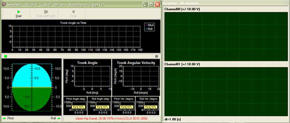
The recording window can be resized as one complete window. However, if a minimum size is reached for the A/D channel display, further reduction of the A/D display is not possible.
The A/D channel displays are of the maximum voltage set in the settings with 1s time graduation along the time axis.
When the recording is completed, or if the Stop record button has been clicked, a message will appear asking if the recording is ok and choice of buttons is presented (YES; YES, but … (the subject lost control of balance); ABORT; RETRY).
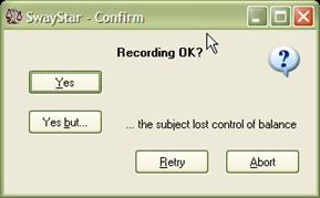
Click YES or YES but … for the following screens, which show first the possibility of adding reference values and second the subject under which data will be saved.
If Bluetooth communication failed during the recording (because the power was at a critical status or the sensor box was too far away from the Bluetooth dongle) a system error message appears. The user can still elect to save the data in this case or use the “Discover Port” function to switch to a serial line COM port and retry the recording.
Adding reference value comparisons
 Reference values are plotted with the analysis. If the data was recorded
with a pre-defined factory protocol then the set of reference values is
assigned automatically. If, however, the recording was done with a user-defined
protocol, you are asked to assign the reference value set, unless you have suppressed
this function (see Settings-operation, section 5.4.6).
Reference values are plotted with the analysis. If the data was recorded
with a pre-defined factory protocol then the set of reference values is
assigned automatically. If, however, the recording was done with a user-defined
protocol, you are asked to assign the reference value set, unless you have suppressed
this function (see Settings-operation, section 5.4.6).
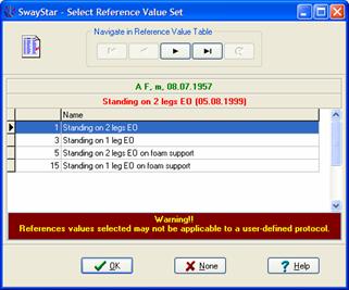
Based on the type of protocol used, the program offers possible reference value sets to assign. For example, when the user-defined protocol is a standing protocol with eyes closed, all similar reference value sets are presented as possible choices. The choice can be changed later (see section 4.5.5: Alter reference set) or the analysis results can be presented without reference value comparisons by selecting None (see below).
If the duration of the recording is less than the lower 5% limit of normal durations for the selected reference set, you are warned that the reference set may not be applicable. Likewise, when if the time window used for analysis is too short, a warning message will appear– see section 5.1.2: New time analysis.
When analysis data are printed, a remark at the bottom, left-hand corner of the printed page indicates whether the reference set was user defined or not and also whether the analysis period was less than 75% of the recording time (for later versions it will be less than the lower 5% limit of the duration for the normal reference). See also section 5.1.2: New time analysis. Median values and 5% and 95% limit bars are printed grey if user-assigned, black otherwise.
Assigning the recording to a subject
When the assignment of the reference value set is completed or skipped, the following message will appear

· The subject is listed in red in the recording window only if the last selected subject and visit is more than 24 hours old (see further description in see section 5.1.2). Make the selection of your choice.
· If you choose to save, you will be transferred to the Save Recording window, shown above, where you can add (+) or select (....) the subject if this has not been done previously.
· It is not possible to add further description in the Record / Test Protocol field. However, you can rename it once stored, see section 5.1.3.
· If you choose YES but… when saving the recording a pictogram indicating a person falling will be shown at the end of the time plots in the analysis screen.