Help for SwayStar™ (4.7.3.265)
Choose your language and SwayStar" will automatically change all text comments to the appropriate language. Currently English, German, Spanish and French are supported.
For interested users who have different languages, you may enter your own translations.
· Enter the root directory for the drive on which SwayStar" is resident.
· Go to BII CH GmbH\SwayStar\Res\String.DEU (if your reference language is German) or String. ENU (if your reference language is English) in the programs folder.
· Use Notepad to edit and save in a new folder labelled String.xxx, where xxx represents the abbreviation for your language.
· Inform BII about the new language (info@b2i.info) so we can update the language list.
To create a new version of a protocol, the edit or add button must be selected. Pre-defined factory protocols can be renamed to become user-defined protocols. To do this, first highlight the pre-defined protocol to use as template. Then click on the add (+) button. The user can give the new protocol the same name or a name different from the original predefined name.
There are up to 2 sets of values to be defined for each protocol: main settings and feedback settings if a feedback type has been selected under the main settings. Currently only auditory feedback is supported.
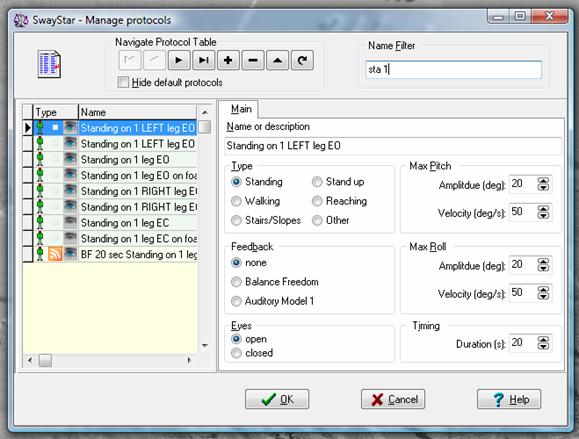
Main recording settings
Here the extent of the trunk angle and angular velocity and the recording duration displays in the recording window can be set. Usually there is no need to change these values from those suggested in the pre-defined factory protocols as these values are only approximate for recording. Auto-scaling is automatically applied to any analysis display. The type of protocol (Standing, Walking, etc. see section 2.4), and whether the eyes are open or closed for the protocol are also set in the main settings.
The type of feedback: none, BalanceFreedom which permits vibrotactile and/or auditory and/or visual feedback to be set, or Auditory Model 1 feedback which uses only auditory feedback.
Balance Freedom Feedback settings
The BalanceFreedom settings can be changed for every protocol. There are 3 levels that need to be set by the user. The user can also decide to suppress use of the feedback settings.
Velocity or Position feedback.
With velocity feedback the feedback is proportional to the trunk velocity of the test person and units of thresholds are deg/s, with position feedback to the angular displacement and units of thresholds are deg.
Acoustic, Vibrotactile or Visual Feedback.
The user can decide to activate any or all of these options. The settings for the feedback are defined within the respective tabs shown below.
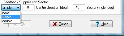
Feedback Suppression Sector.
The user can decide to deactivate a sector for the feedback. If none is set no sector is deactivated. If simple is set, the centre direction for the sector must be set (Note 0 deg is forward, 90 deg is right direction, 180 deg backwards and 270 deg left.) and the sector angle. The sector deactivated is then 0.5 the sector angle either side the direction angle. If double is set, the mirror image sector (point symmetry) is also deactivated.
It is possible to just have a small sector active by defining a large sector angle. For example direction 270 deg, sector angle 270 deg would mean only 90 deg sector 90 deg would be active.
BalanceFeedback Auditory Settings.
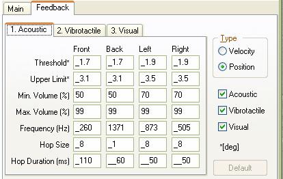
For the acoustic BalanceFreedom settings, the thresholds and upper limits of sway to which the feedback responds in each direction need to be set. Likewise, the sound volume of maximum that the two bone-conducting transducers are activated at between these limits must be set. Between threshold and upper limit the sound volume is increased linearly. The feedback works by activating the left bone conductor with one frequency when the subject sways to the left, the right bone conductor with another frequency for sway right, and both conductors for sway forwards or backwards. Thus, the frequency of acoustic stimulation needs to be set for each sway direction. This frequency can be oscillated across nearby frequencies (see Hop size in the settings below). The new frequency is changed at intervals set under the setting Hop duration. The bone conductors are arranged in the headband of the BalanceFreedom system so that these are placed over the mastoid processes above the ears.
The acoustic settings shown below are the default settings and are applicable for young (20-30 years of age) subjects performing the task of standing on 1 leg on a firm surface eyes open. For these settings the threshold ordering is vibrotactile, acoustic and then visual. Generally settings are arranged to be task dependent (see references in section 2.2), but can also be individually set.
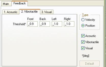
BalanceFeedback Vibrotactile Settings.
Vibrotactile feedback is set on or off dependent on directional specific thresholds as listed below for the default setting. Usually vibrotactile feedback is set on before acoustic and visual feedback. The vibrotactile feedback transducers consist of 8 vibrators arranged in the headband of the BalanceFreedom system, each being activated when sway is in direction of the transducers.
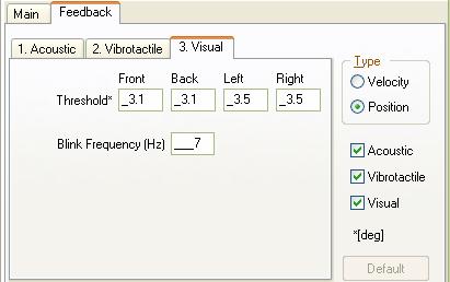
BalanceFeedback Visual Settings.
The visual feedback is considered to be an alarm signal for the BalanceFreedom system. Hence it is set on or off at a greater threshold than the auditory or vibrotactile feedback.. The thresholds as listed below are for the default setting. The LEDs on the BalanceFreedom headband are set flashing with a frequency when sway exceeds any of the directional thresholds.
Typical BalanceFreedom assessment and rehabilitation schedule for patients with chronic balance problems due to peripheral vestibular loss.
Initial Balance assessment:
WEEK 1 (3 training sessions of about 30 mins)
Training session 1: Monday
Patients perform the BalanceFreedom training protocol consisting of repeated training with feedback on a subset of the tasks used in the initial assessment (Table 2). Patients are instructed to stand or move during the training so that the feedback signals are not active, that is trunk sway is reduced as much as possible. The last trial of each protocol is recorded for following patient progress.
Training session 2: Wednesday
Patients perform the BalanceFreedom training protocol consisting of repeated training with feedback on a subset of the tasks used in the initial assessment (Table 2). The last trial of each protocol is recorded for following patient progress.
Training session 3: Friday
Same as session 2.
Second Balance Assessment: Friday
WEEK 2
Training session 4: Monday
Patients perform the BalanceFreedom training protocol consisting of repeated training with feedback on a subset of the tasks used in the initial assessment (Table 2). However, biofeedback onset thresholds will be based on their second balance assessment values. The last trial of each protocol is recorded for following patient progress
Training session 5: Wednesday
Same as session 4.
.
Training session 6: Friday
Same as session 5.
Third Balance Assessment: Friday
Table 1:
|
Balance tasks |
30 secs Standing feet together EO |
|
Assessment |
30 secs Standing feet together EC |
|
|
20 secs Standing on 1 leg EO |
|
|
30 secs Tandem Stance EO |
|
|
30 secs Tandem Stance EC |
|
|
30 secs Foam Standing feet together EO |
|
|
30 secs Foam Standing feet together EC |
|
|
Walk 8m EO |
|
|
Walking 3m pitching head |
|
|
Walking 3m rotating head |
|
|
Walking 8 tandem steps EC |
|
|
Walking 8 tandem steps EO |
Table 2:
|
Balance tasks |
30 secs Standing feet together EC 6x |
|
Training |
20 secs Standing on 1 leg EO 3x |
|
|
30 secs Tandem Stance EC 2x |
|
|
30 secs Standing feet together EC Foam 2x |
|
|
Walk 8m EO 5x |
|
|
Walking 3m rotating head 5x |
|
|
Walking 8 tandem steps EC 5x |
Auditory Model 1 Feedback settings
The auditory Model 1 feedback (AF) settings can be changed for every protocol. There are 4 levels that need to be set by the user. The user can also decide to suppress use of the feedback settings.
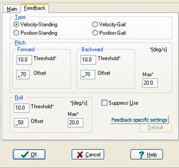
Velocity or Position feedback. With velocity feedback the feedback is proportional to the trunk velocity of the test person, with position feedback to the angular displacement. The threshold, maximum and minimum values, can also be set differently for stance (standing) and gait.
Thresholds which must be exceeded for the AF to produce a sound. These can be set differently for pitch backwards and forwards, and roll. The default values set in the AF hardware are as follows:
|
|
Velocity |
|
Position |
|
|
|
Stance |
Gait |
Stance |
Gait |
|
Pitch Forwards |
3 °/s |
10 °/s |
0.5° |
6° |
|
Pitch Backwards |
3 °/s |
10 °/s |
0.5° |
3° |
|
Roll |
2 °/s |
10 °/s |
0.3° |
2° |
Where Stance thresholds are for standing protocols and Gait for walking, sit-to-stand and other protocols involving locomotion.
Maximum values which when reached the AF system does not increase in its sound volume further. The default values set in the AF hardware are as follows:
|
|
Velocity |
|
Position |
|
|
|
Stance |
Gait |
Stance |
Gait |
|
Pitch |
20 °/s |
50 °/s |
15° |
15° |
|
Roll |
20 °/s |
50 °/s |
15° |
15° |
Minimum (Offset) values of sound used where the AF thresholds are exceeded. These are set by default for the 4 loudspeakers as follows:
Front 60 dB SPL (A) Rear 75 dB SPL (A)
Left 60 dB SPL (A) Right 60 dB SPL (A)
It is recommended that a louder effect be used for the rear loudspeaker because of the shadow effect of the ears. The maximum volume (ca. 90 dB SPL (A) and the frequency of each loudspeaker tone (left 1000 Hz, right 900 Hz, front 500 Hz, rear 1500 Hz) cannot be changed. Note: When these values are set by the protocol during a recording, these become the default hardware values set in the SwayStar" AF controller box. If the user tries to record with an AF protocol and the feedback controller is not switched on then a warning will appear.
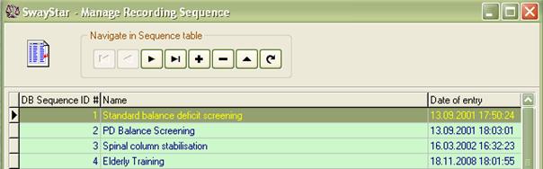
Sequences (Normal and BalanceFreedom)
To create a new sequence, click the + navigate button to add a sequence. The following screen will appear.
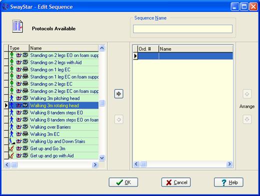
Select the available protocol
and move it to the right-hand panel by clicking on the  arrow.
Change the order of the selected protocols by using the
arrow.
Change the order of the selected protocols by using the  or
or  buttons. Use
  arrow
to remove a protocol after first clicking on the protocol in the right-panel
that you wish to delete from the sequence. A number of default sequences
are available:
arrow
to remove a protocol after first clicking on the protocol in the right-panel
that you wish to delete from the sequence. A number of default sequences
are available:
The same procedure is used to create BalanceFreedom sequences for uploading into the stand-alone BalanceFreedom controller when it is connected to the SwayStarTM sensor unit.
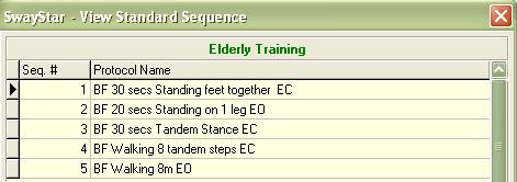
There is one default BalanceFreedom sequence which has protocols for training the elderly.
In cases where different printers or difference paper size, or other printer variables change as a result of several printers being available within one clinical facility, this option reminds the user to select and set-up the appropriate printer and its parameters.
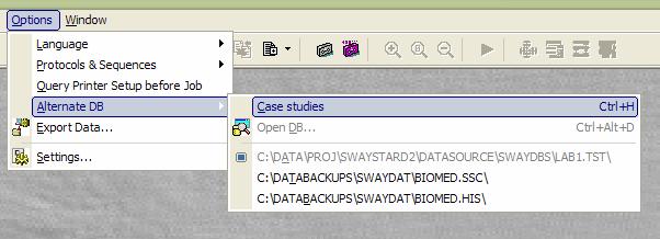
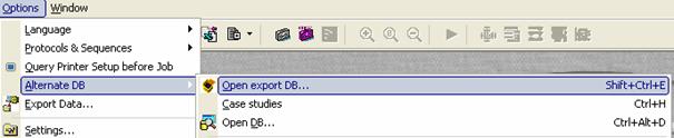
SwayStar" can work with different databases that all have the name BIOMED.xxx existing on different logical devices, provided the operation setting that switches to alternative databases is ticked (see Main Menu/ Options/ Alternative DB). The user can search for an existing database or create and open a new database.
Sample Case Histories
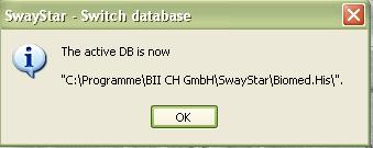
SwayStar" also has a special database of case histories containing typical patient results (see section 7. Sample Case Histories). The user may select the Case History database, but once selected can not modify the entries or make any recordings.
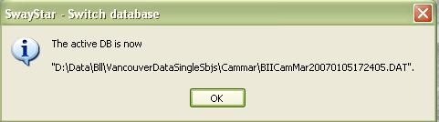
You will then be informed that this data base is active:
User Databases
The user may choose to open an alternative database of user data. If you wish to open an alternate database, select Open DB (as shown above). This opens a new dialog shown below.
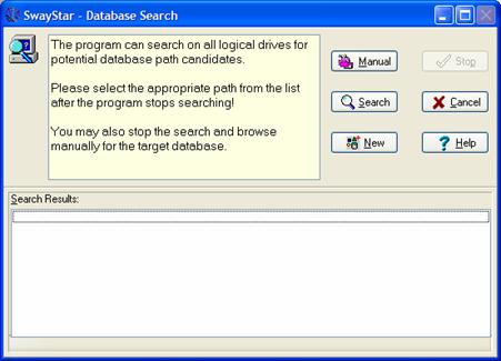 Within this dialog
by clicking the corresponding button the user can search automatically
Within this dialog
by clicking the corresponding button the user can search automatically

or manually 
for all possible SwayStar"
databases on the host computer and its associated network drives. In the
case of the automatic search a list of all possible DB candidates is
generated from which you may select the DB of choice. Whether the search
procedure is stopped or completed, you may still search for a DB manually
or generate a new DB clicking the button  .
.
If you attempt to start SwayStar" with a DB selection located on a server to which the user is not connected the following error message appears:
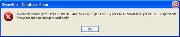
A new DB section must be made or the drive mapping must be restored.
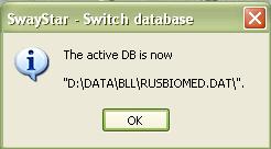
Once the data base has been located and activated the user is informed.
Export Database
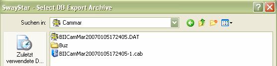
The user may receive a by SwayStar" encrypted exported database from another user. The procedure for opening this data base is the same. First select the command, then the file and finally the selection will be confirmed.
In addition, dragging a DB-Folder or an archive onto SwayStar" opens the corresponding DB. An archive is extracted in the folder of that archive.
Assume BIIBilLos20070121154907.7z.001 is the name of the archive the DB Folder is named BIIBilLos20070121154907.dat. If an archive is dragged from a E-Mail the file is extracted in the %temp% folder. In this case when restarted SwayStar" opens the previously opened DB as this file dragged from an email was only temporary active.
In order to export any data, any logical drive connected to the PC can be used. For security reasons (patient data over internet) the export data base is encrypted. Starting this option automatically requests definition of the device and the path. It is possible to export all recordings from a single visit or all recordings in all the visits of a subject (in other words a complete subject). For selection purposes, the retrieve data window (see section 5.1.1) is opened automatically.
Acknowledgement: The encryption procedures is an open source Delphi VCL for 7zip format see http://www.7-zip.org)
Note: The directory will need to be defined properly in the box provided. The maximum size and type of the file should have been defined see Settings, section 5.4.6, Export.
After the export process is complete it may be automatically emailed to BII in cases where troubleshooting is requested.
There are four steps to Exporting data.
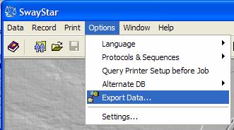
Step 1:
Under Options, select Export Data
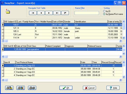
This will bring you to the Retrieve Records
Window (below)
Step 2:
Select the subject, visit or single trial you wish to export and double click the left mouse button.
 Step 3:
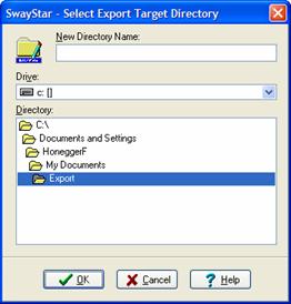
· Specify the directory.
· Select the drive and the directory.
The subdirectory name entered in the field New Directory Name is created relative to the directory selected with the navigational controls.
Note: A fully qualified name entered in this field (i.e. C:\DATA\EXPORT) overrides navigation selected in Drive and Directory.
Step 4:
The Export function is completed by click OK
If you wish to send the data to BII either for the purpose of requesting information or to request troubleshooting, click in the white box and then on OK.
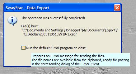
This will automatically open an email window.
Step 5:
To use the export file.
Unpack the cab file to the directory, using the manual search function of SwayStar" under Options-Alternate DB Open Export DB to locate the export directory, chose the directory and double click on the subject.db file. The data can now be retrieved normally, provided Allow switching to alternative data bases has been set under Settings.
Alternatively, when many patients are involved, it may be easier to copy the whole biomed directory on the source computer to another biomed directory on the host computer, rather than export individual patients.
Operation
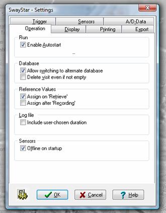
Run
Enable Autostart (control A): Choose this if you wish for SwayStar" to open automatically when your computer is first booted.
Enable Autostart on an end-session condition (control E): Choose if you wish SwayStar" to open again should it still have been open on powering down the computer.
Database
Allow switching (control W) to alternate database
Delete visit even if not empty: all records will be deleted from the visit folder. If this is not chosen, in order to delete a visit folder, the user must first delete each record in the visit separately and then delete the visit folder. (See section 5.1.3, Visit, for further description.)
Reference values
At end of recording no reference set assignment for user defined protocols
On data retrieval no reference set assignment for user defined protocols. This setting is only useful for users who have data recorded with user-defined protocols prior to SwayStar Version 4.0.0.120, that is prior to having reference value assignment.
Log file
Enable the user selected duration for analysis is to be entered into the log file.
Sensors
Ensures that the sensors are offline, and communication is not attempted when the program is started. The default setting is online after installation.
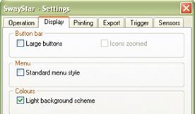
Display
Choose the size of the icons to be displayed. Larger icons require two rows in the tool bar.
Change the background colour of the display to white or leave it black.
Printing
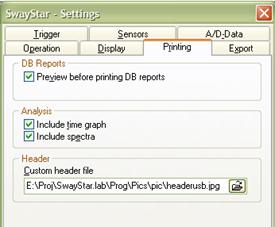
Some or all of the graphs appearing in the analysis window may be sent to the printer. (See section 4.2 for further explanations)
Preview print (control v) before printing DB (database) reports.
The Analysis may be printed with or without the pitch time or roll time plots (time graph) or without the spectra depending on the print settings and printer capacity. A header may be added to the printed sheets. The default header is from BII. An operator may create and select his own header. The width of the header image should be at least 800 pixels and the width to height ratio should be between 9.5 and 9.7
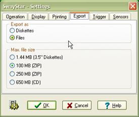 Export
The type of file (floppy or to a logical drive ) and its maximum size can be defined.
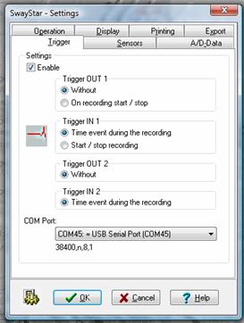
On request BII will supply the trigger box for connection to a USB port via a COM port convertor.
This trigger box has 2 BNC connectors for an inbound trigger signal and 2 BNC connectors for an outbound connectors. When the trigger function is enable in the software, a COM port for the trigger must be defined, otherwise an error message appears. It is reccomended that the USB port of laptop computers is set switched on on battery low.
Outbound triggers OUT 1 and OUT 2
OUT 1 can be programmed so that SwayStar" provides a triggering signal at the BNC connector setting a TTL pulse high on recording start and low on recording stop, or it can be without output.
OUT 2 is always without output
Inbound triggers IN 1 and IN 2
At the IN 1 connector the leading edge of a TTL signal can be used to start SwayStar" recording and and stop the recording with the falling edge.
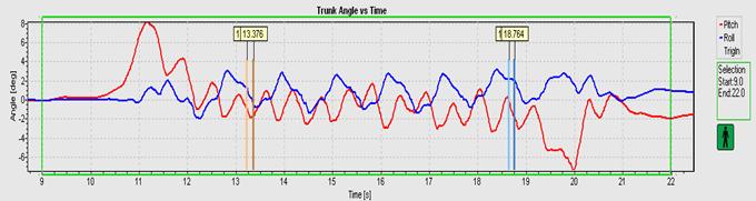
At both IN 1 and IN 2, TTL signals can be set to mark events on the time plot of trunk pitch and roll. Two markers are set for each signal, one on the leading and one on the trailing edge as shown by the example below of a young normal walking past to light barriers which sent TTL signals to IN 1 and IN 2. The first marker of the pair is a light colour and the second a dark colour, each marked with the time of the marker event as shown below.
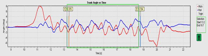
The data analysis window can be set to the triggered markers by placing the cursor on the marker bar. A vertical arrow appears. Press Ctrl plus the Windows button and left mouse click to set the lower time limit of the analysis window, and Alt plus Windows button and left mouse click to set the upper time limit to the analysis window. The result appears so:
To set the analysis window on the correct marker event it may be necessary to zoom the recording and then to drag the area of interest into the centre of the time plot using the right mouse button.
Sensors
See section
3.2.4 for full description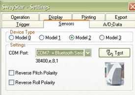
Note: It is possible to change the polarity of the sensors for both Pitch and Roll. Changing the polarity only affects the way in which signals are depicted on the display monitor.
 The A/D Data tab
is only available after installing the Data
Translation DataAcq Omni CD that installs
the DT Open Layers for Win32 software.
The A/D Data tab
is only available after installing the Data
Translation DataAcq Omni CD that installs
the DT Open Layers for Win32 software.
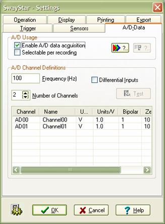
The mode of data collection and the channel definitions for A/D data collection can be defined for the DT9800 A/D converter used with SwayStar".
Buttons with ? can be clicked to obtain information about the external A/D convector box and its properties.
Checking the box enables A/D data acquisition means that analogue data is always recorded, whereas selectable gives the user a choice whether to have A/D data or not when the recording is started.
The button Test allows settings to be tested with respect to those the A/D board supports.
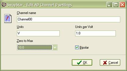
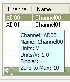
The A/D channel values, name, units, units per volt and the zero to maximum voltage range can be set by double clicking on the line in the box with the channel listings or highlighting the line in the box and then striking enter.
The current values are displayed as a hint when the mouse passes over the line.